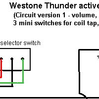
Westone Thunder active guitar wiring
This diagram is based on the
wiring in a January 1983 Thunder IIA. It should be suitable for any Thunder active guitar with controls
for volume, tone and active gain and 3 mini switches for coil
tap, phase reverse, and active on/off
Notes:
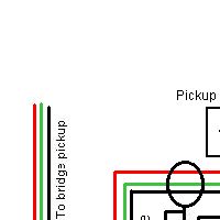
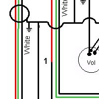
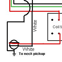
- the white wire from the neck pickup connects directly to the red
wire on the shielded cable to the pickup switch. The join is wrapped in
insulated sleeving
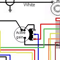
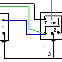
- there is a pcb on the back
of the phase switch which provides the interconnections between the
terminals. If the switch needs replaced the pcb is not needed and can
be replaced by 2 link wires as shown
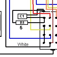
- this is a bare wire which
connects to single terminals on the coil tap and phase switches and
also is soldered to the bodies of all three mini switches
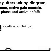
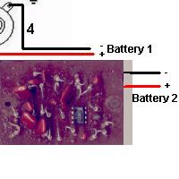
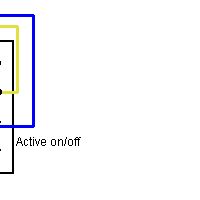
- this battery earth connects
to the switch terminal on the (3 terminal) jack socket - the circuit is
completed when a jack is inserted, connecting this terminal to earth.
- One end of R1 and C1 connects to the switch terminal, the other end of both components is soldered to the switch body
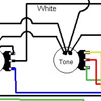
The coil tap and phase mini switches are DPDT, the active bypass
switch is a 4 pole changeover switch. The volume pot is 500K
log, the gain pot is 250K log and the active tone pot is a 500K linear pot with a centre detent.
Resistor R1 is 1 meg, capacitor C1 is 0.022 microfarad mylar.